Sunday 29 January 2023

Fowler Rebuilding

In my last post on the Fowler F 30 I had just finished taking the loco completely apart. With the buffers removed I could mark out where to drill new holes for a lower buffer position. The holes themselves were drilled out to 3.5 mm with metal drills and cleaned up with files. 

Rear buffer in new lowered position. The upper half of the hole for the old position can be seen.

The front buffer wasn't as straightforward as the rear buffer. A large ballast weight was positioned up against the buffer plate from the inside and had to be altered to mount the buffer lower. As the weight was mounted close to the blind axle, I had to unscrew the front buffer plate to remove it. Once out, I cut the upper part of the ballast weight off with an angle grinder and refitted it before I screwed the buffer plate (with a new hole drilled in it) back on again. Reducing the amount of weight at the front end of the loco is no problem, as the old battery pack was far heavier than the 9 V battery to be fitted. Both buffers were mounted in their new holes and the buffer height tested with my three types of skips.

Front ballast weight before modification. The two holes are for mounting the weight in the loco's footplate, the single hole is for the buffer mount. The upright part of the weight was removed.

Front buffer refitted in lower position. Here seen coupled to a Hudson 'Rugga' skip.

As a result of my selection of a much smaller battery size I got the possibility to remove the large battery box in the cab and rebuild the cab area. Once I had the battery box in the cab removed I drew up a list of features I would like to show in the open cab. The list included wooden floor, platework separating cab and engine room, brake stand and levers, instrument panel with light, seat and a driver figure.  
New cab floor made from plasticcard. The floor is built as a module that slips between the loco's frames. The floor module can be lifted out in one piece for servicing and fitting of wires and battery.
,
The floor seen from above. Boards were scribed with a small screwdriver and the surface distressed with knifeblade and coarse sandpaper to produce wood texture.

When I removed the large battery box that protruded into the cab, it left a large opening between cab and bonnet. The opening was closed with a plasticcard cover detailed with a hatch for relatively easy access to the engine room. I added a few bolt heads from octagonal plastic profile. The complete cover plate was AC-glued to the innerside of the cab front.

Fowler cab fitted with new floor and front wall cover.

With the large openings in the cab details inside the cab will be easily viewed. Here is a rear view of the cab interior.

With lowered buffers and basic interior in the cab I will move on to building an instrument panel and brake stand to be fitted in the cab as well as preparing the loco for installation of a new battery. 

Friday 20 January 2023

Taking The Fowler Apart

As delivered the Essel Engineering Fowler is equipped with a huge battery pack and manual control via toggle switches in the cab and chimney. That's probably not too bad on a garden railway with few directional changes and long or continuous runs. On a very short layout manual control is (in my view, at least) unpractical, even if the chimney speed control actually worked fine. Having had good experience with the RC equipment built into my little Lister it was obvious that the Fowler also had to be remote controlled. 

Disassembly in progress. The large battery box with fuse and connecting wires is seen to the right. In the middel the electric motor and gear box. To the left is the handle for regulating speed.

The battery pack in the Fowler consisted of 6 AA-batteries. Testing the top speed showed that the battery pack could propel the loco a lot faster than it would ever be realistic on my model railway. With a small layout I also don't need the same endurance as a garden railway operator and I decided to cut down on battery size to a single 9 V battery. Testing showed that it produced at satisfactory top speed. In exchange for a reduced battery size I would have possibility to remove the large battery box in the cab, rebuild the cab area and fit a driver figure. See a short sequence from the initial running in of the locomotive in its original condition.


To remove the batteries and original control equipment I had to dismantle the model quite substantially. I first took off the cab by removing the screws in the rear buffer plate. Once the cab was removed the screws holding the large battery box in place were unscrewed and the box lifted off and toggle switches and charging socket removed. The chimney (exhaust pipe) was lifted off and the bonnet taken off. Then I removed the speed controller and was free to conduct final dismantling of the complete network of wires. 

Difference in buffer height between Fowler and standard skips. Something has to be done!

As I had the loco almost completely taken apart I took the chance to lower the buffer height as my stock of small skips obviously wasn't compatible with the original buffer height. I have now removed the buffers and will carefully drill new holes. While the rear buffer will present no obvious challenges the front buffer will need the front ballast weight modified. Looking forward to the work, though!

Rear buffer removed. New hole to be drilled for a lower buffer height.

Sunday 15 January 2023

Underground Skip Progress

In my last post on the Hudson U-tub underground skip I had just finished hand pushing one half finished wagon along the Nystrup Gravel track. Since then I added a little weight in the tub (a 12 g pipe fitting) and made some tests with loco pushing the skip along the track through points and curves. Everything seemed to work tolerably well.

The Lister Rail Tractor test pushing 3 skips - so far without any derailments.

Once the testing on one skip had been carried out I prepared parts for two more wagons. I subscribe to the view that 3 examples of an item is seen as 'many'. Probably because the eye easily recognises two as a 'pair', 3 seems to put more strain on the brain. No matter what I now have 3 assembled skips that I will continue to work on. I will gather experience and only then assemble the last 3 skips. 

Prepared parts for two skips laid out on the worktable.

As I mentioned the skips' very light weight is a serious obstacle for reliable running on my uneven track. With a weight of the frame of only 6 g, wheels and axles 7 g and the tub weighing 12 g, I added 10 g of additional 'ballast' gaining a total weight of 34 g. Even with the 3D printed wheels the test wagon worked alright, although more weight wouldn't hurt. It remains to be seen how much weight I can fit in.

Blog reader Nick Curtis commented that Slaters Plastikard's 6 curly spoke 16 mm diameter wheels (ref. 1612DIN) could probably fit on the skips and I'm now considering to replace the plastic wheels. I'm trying out the kit wheels first to give them a chance, though. Surely the advise and hints I'm picking up from the blog's comments is a valuable source for improving my modelling.


The wheels that may find their way to replace the kit's 3D printed wheels.

Once the final rolling tests and weight experiments have been carried out I will take the 3 skips apart again and figure out how to fit coupling chains and hooks. I will also be working on how to add some texture to the skips to represent rust, flaked paint and caked on ash and debris. More about that later.

A U-tub skip being loaded by a Eimco 12B rocker shovel at the Lea Bailey Light Railway. The skip has similar tub details as my Hudson skips, but has a different frame. Image: LBLR. 

Friday 6 January 2023

Underground Skip on Track

With Christmas and New Year celebrated and having settled stage 1 of the work associated with my daughter's wedding and new apartement, I finally got half an hour at the hobby table. The result was a rolling 3D printed Hudson underground skip, one of six that arrived shortly before Christmas. A lot of work still remain, but as a 'proof of concept' the result was satisfying enough.

U-tub skip for underground use next to a standard Hudson V-skip. 

With a 3D printed construction a small model like the Hudson skip is extremely light - even in a scale as large as 16 mm. With some rather coarsely printed wheels thrown under the construction I expected a model with less than mediocre running qualities. To enhance running replacement metal wheels would be a natural solution, but as I haven't yet found any metal wheels of the correct type I'm going to use the printed ones for a start. That means that I have to cram as much weight into the skip as possible, preferably as low as possible to avoid a high centre of gravity.

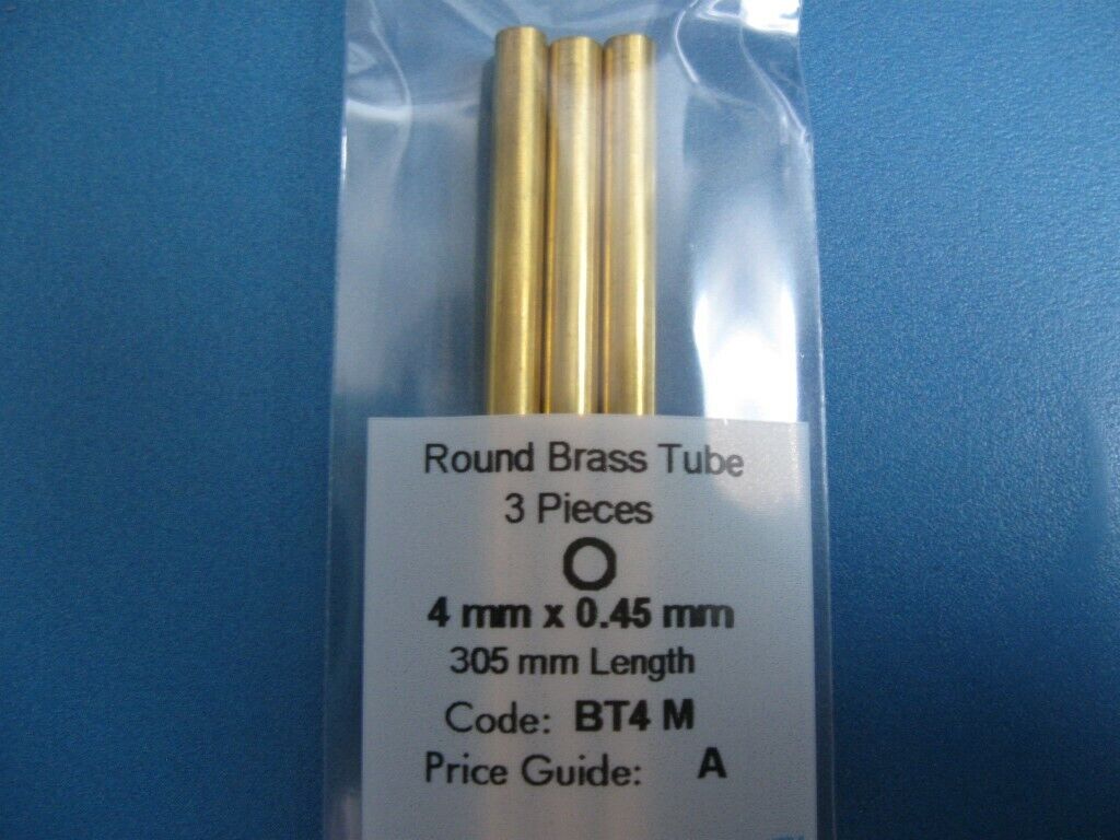
First I had to get the skip running. The wheels are designed for 3 mm axles and I ordered axles as well as brass tube with a 3 mm internal diameter to fabricate bearings. When arriving the brass tube turned out to be 5 mm outer diameter and impossible to fit in the model's axleboxes without wrecking them. It turned out that Albion Alloys had thin-walled brass tube with a 4 mm outer diameter. The tubes were even available from a Danish seller, SMT- modeltog, making a delivery to my door in less than 48 hours possible. To make the postage worth the investment, I added some glues to my order. 


BT4M brass tube with 4 mm outer diameter and inner diameter of 3,1 mm. 

Picking a skip frame, I quickly sanded most of the printing traces from the sides of the frame and opened up the holes in the axleboxes to 4 mm. To make the wagon a few grams heavier, I decided to cut a single, long brass bearing completely enveloping the 3 mm brass axle instead of two bearings fitted into the axleboxes on each side of the skip. With limited view of anything below the skip's tub I think the slightly larger appearance of the axle will hardly be noticed. The axles were cut to length (39 mm even if the instructions said 42 mm). The wheels' axleholes were reamed with a 3 mm drill, the axle fitted in the tube bearings and the wheels pushed on. Before fitting, the wheels were cleaned up a bit and the worst dimples on the running surfaces removed. The wheels are by no way worse than what I have seen on prototype industrial narrow gauge rolling stock in Denmark. In model they may need further treatment, though.

Tube bearings, axles and wheels fitted. The wheel profile isn't the prettiest I've seen!

Skip frame on my Code 100 test track undergoing the first rolling test. 

The first finger pushing tests conducted on a test track and the on the real Nystrup Gravel track, showed that he wagon behaved quite well, even on uneven and curved track. Next up is adding a little weight in the tub and making tests with loco pushing. Once the rolling tests and weight experiments have been carried out I will take the skip apart again and figure out how to fit coupling chains and hooks. Then it will need sanding and add ing of texture, painting and weathering. And then there is five more waiting! I have previously done assembly line work on identical models and I will probably do the same on the underground skips.

All parts for a single skip brought together on my worktable test track panel.


After being hand pushed on the layout with reasonably succes the U-tub skip is now resting, waiting for further tests and improvements.